Jordan Hydroelectric Project
Summary
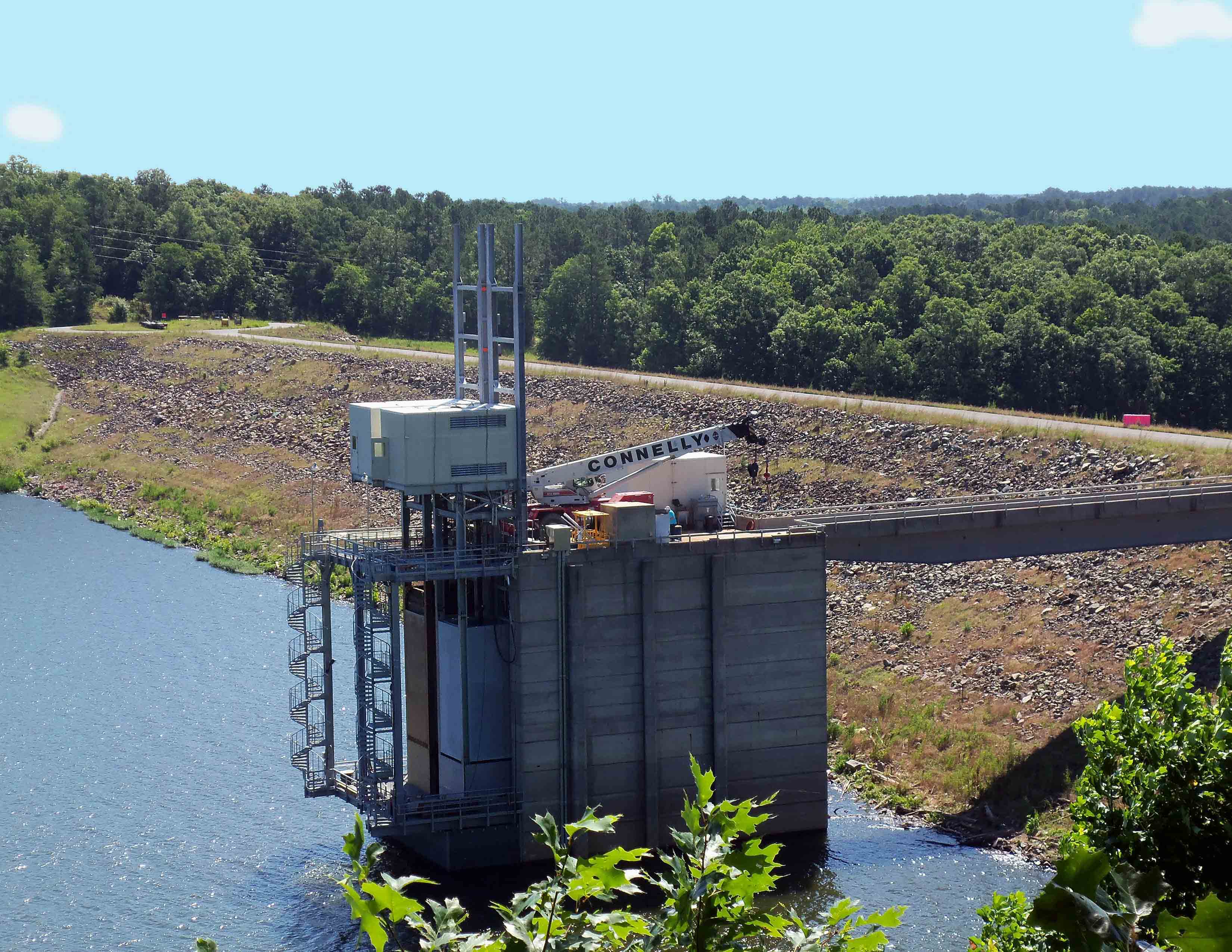
The Jordan Hydroelectric Project is the first hydropower facility of its kind in the country, using vertical turbines installed on an intake tower at a U.S. Army Corps of Engineers flood control dam. It involves the installation of two conventional vertical Kaplan turbine-generators, each with a capacity of 2.2 MW under 57.5 feet of gross head and flow of 550 cubic feet per second, installed in a 180-ton steel enclosure (power module) that seals (like a headgate) to the upstream side of the tower’s intake. Due to the adjustable nature of the design, power can be generated nearly 95% of the time without sacrificing any of the normal or flood control capabilities of the dam.
The project was completed at an economically installed cost of approximately $2,300 per kW inclusive of all development, design, equipment, and construction costs (construction of a hydroelectric project in a new powerhouse at an existing dam typically has an installed cost of $4,000 to $5,000 per kW). The lower installed cost for the project is the direct result of not needing to construct significant civil works to house the power generating equipment. The average annual generation is estimated at 16,900 MWH, with the project producing enough electric power for 1,700 homes. The project developed an untapped power source of an existing dam which since 1982 could have generated 500,000 MWH.
Background
The Jordan Dam was constructed in 1982 as a flood control dam without hydroelectric generating capacity. Located in Moncure, NC, 25 miles southwest of Raleigh, the main dam is a rock-filled structure 113 feet high and 1,200 feet long, owned and operated by the U.S. Army Corps of Engineers (USACE) for purposes of flood control and maintaining water quality of the Haw River.
Licensing of the hydroelectric project with the Federal Energy Regulatory Commission (FERC) began in 1993, with a license received in 1997. The initial concept was for an 8.0 MW project consisting of two Power Modules with eight to ten small horizontal turbines in a matrix arrangement. The license was amended in 2006 for the current two-unit, 4.4 MW hydroelectric project after it was determined that the original arrangement had a number of technical challenges associated with it.
Challenges
The project developer and design team faced several challenges including that the design and operation of the project had to comply with USACE design and operational requirements. Paramount of the design and operational requirements was that the project could have no effect on USACE’s control of flow releases or operation of the tower and negligible modifications would be allowed to the discharge tower.
The slender, torsionally light Power Modules also had to resist or transfer to the intake tower the rotational torque developed when generating power; a torque that for conventional powerhouses is typically resisted by anchor bolts and mass concrete. Under normal operation, the generator develops a torque of 51,250 foot-pounds and a short circuit torque of 243,000 foot-pounds. The USACE also expressed concerns for the transmittal of vibrations into the tower from the mass of the rotating equipment.
The requirement of minimum impact to the tower coupled with the low load capacity of the existing structures also presented challenges to the engineering team’s design and installation plans. Final modifications to structural elements of the discharge tower only required the removal of a parapet wall at the top of the tower along the upstream side, and removal of two 13 foot square by 3 feet thick underwater sections of concrete that formed the top of the existing concrete grizzly racks. Structural analyses of the access bridge from the dam crest to the top of the discharge tower indicated that the bridge has a sufficient structural capacity of 250 tons. However, analyses indicated that the discharge tower roof, which was designed to support a 35 ton truck crane transporting a 12 ton load, did not have the capacity to support the weight of a 90-ton rough terrain crane and the loads to be lifted.
In addition, a survey of the plumbness and squareness of the bulkhead slots taken at one foot increments over the height of the tower from invert to roof revealed another challenge for the designers. The distance between piers was narrower than shown on record drawings and the slots were neither plumb nor square to the tower.
Innovation
To address the operational requirements to be able to pass flood flows, the team developed a modular design that houses the hydroelectric units and allows the Power Modules to be raised to pass flood flows and allow maintenance of the equipment, and lowered to allow power generation. Each turbine has a hydraulic discharge capacity of 550 cfs and each Module contains two spill gates with a discharge capacity of 500 cfs each. The project’s Modules can control a flow of up to 3,100 cfs through the turbines and spill gates, flows that occur 86% of the time. Power has already been generated with a Module raised up to five feet with 5,000 cfs being discharged beneath the Module for a total discharge of 8,000 cfs a flow that is exceeded only 5% of the time.
The design includes two conventional vertical Kaplan turbine-generators, each with a capacity of 2.2 MW under 57.5 feet of gross head, installed in a steel enclosed Power Module that seals (like a headgate) to the upstream side of the tower’s intake. Each of the project’s two Power Modules contains a single turbine directly coupled to a synchronous generator, with the generator located 60 feet above the turbine. A weather proof enclosure houses the generator along with a hydraulic power unit and electric control systems need to operate the power-generating equipment. The Power Modules are 13 feet square and 77 feet high from the invert to the generator floor, with an overall height of 120 feet. The Power Modules have a gross weight of 180 tons inclusive of 54 tons of power-generating equipment. The Power Modules are located upstream of the tower’s emergency and services gates, in existing maintenance bulkhead slots. Project switchgear and station service transformer are located in a booth that was cantilevered off of the intake tower.
A novel lifting system was designed that consists of a single 200-ton hydraulic cylinder per Power Module with a 12-foot stroke to raise a Module in 10-foot lifts. The lifting carriage has two rotating cam arms, operating similar to a forklift, that engage a series of steel lift blocks located on the downstream face of the Module. The Module is raised and lowered under balanced head conditions. When being raised or lowered, a Module is temporarily supported by dogging devices while the lifting carriage is repositioned to reengage the Module for another lift. This innovative lifting system allows the Module to be raised or lowered 40 feet by one individual in 45 minutes to pass flood flows. The Modules can be lifted up to 67 feet to raise the turbine runner above the lower access platform to facilitate maintenance.
All operations of the Power Module and power generating equipment are automated when raising a Module. The automated operations include shutting down and locking out the turbine-generator, opening of the Module spillgates to flood the tower downstream of the Module, and retracting of the screw jacks. Once the intake tower is flooded and hydrostatic pressures equalized on the Module, the lifting of the Module begins with a push of a single button. The operating personnel must manually initiate the closing of a USACE gate to allow the tower to be flooded, and that personnel must initiate opening of the same gate once the Module has been raised to the desired level.
To address the rotational toque developed by the generator, each module has six electrically operated screw jacks located at the generator floor which are extended to “lock” the generator floor to the tower bulkhead slots. These jacks resist the generator’s normal running torque of 51,256 ft-pounds (8,543 pounds at the jacks) and short circuit torque of 243,000 foot-pounds (40,563 pounds at the jacks). The jacks are extended before operating the turbine and retracted prior to raising or lowering the module.
Vibration is monitored continuously by a control system and the generating equipment will automatically shutdown if vibration limits are exceeded. A rotating machinery testing and balancing firm tested the equipment for balance and vibration and determined that vibration was well below that normally accepted for rotating equipment. Displacement measurements and values aside, vibrations are low enough that a penny can be stood on edge on the generator housing and will remain in that position for 30 or more minutes, eventually falling over due to air currents inside of the generator enclosure. Higher vibrations are recorded when the unit is offline and water is discharged through the existing tower gates. There are no increases in vibration when the unit is operated with discharges occurring through the tower gates.
The construction logistics of access and load capacity of existing structures had significant impact on the design and resultant weight of individual sections of the Power Modules. The 90-degree turn needed from the dam onto the access bridge to the intake tower necessitated the use of a conventional short-bed, dual axle equipment trailer that could be jackknifed onto the bridge by a rough terrain fork lift, with the trailer loaded to 75% of its structural capacity. In addition, the discharge tower’s roof was originally designed to support a truck crane with a 90,000 pound GVW when transporting its design load while a 90 ton rough terrain crane, with a GVW of 115,000 pounds was required to lift sections of a Power Module weighing up to 62,000 pounds. The roof’s capacity restrictions necessitated stripping the crane down to 83,000 pounds by removing the counterweights, jib boom, and crane hook, and the crane’s boom was raised to 57 degrees to evenly distribute the loads on the axles when being positioned on the tower. Finally the crane was set up on a set of three 21-inch high steel beams spanning the width of the tower to transfer all crane loads to the tower’s side walls.
Design modifications and in-field problem solving were required as a result of the discharge tower not having plumb or square guide slots along its upstream face where the Power Modules were installed.
Results
The project is unique in application by taking existing, proven hydropower technology, installing it in a location that has been historically overlooked as a potential power source, and cost-effectively producing renewable power under a range of flow conditions. The project was completed at an economically installed cost of approximately $2,300 per kW inclusive of all development, design, equipment, and construction costs whereas construction of a hydroelectric project in a new powerhouse at an existing dam typically has an installed cost of $4,000 to $5,000 per kW.
The lower installed cost for the project is the direct result of not needing to construct significant civil works to house the power generating equipment. The steel Power Modules that house the generating equipment were manufactured and assembled off-site and installed in large sections, eliminating the need for on-site “stick-building” of a powerhouse.
While the engineering concept and many of the operating systems were custom designed to fit the site, accessibility, and operating requirements, many of the project components can be adapted and economically installed at other similar dams, USACE or otherwise, that contain an intake tower. The project did not utilize any proprietary or patented design, equipment, or operating systems and adoption of the project’s concept in other locations can be cost effectively implemented, resulting in the generation of additional renewable energy from an existing dam.
Stakeholder Quotes
Project Developer Jim Price, President of JHLP stated, “The design done by Kleinschmidt and NFEI overcame several complicated aspects of the installation of hydropower at Jordan Dam. Their collaborative solution allowed the project to be completed at a very competitive cost in today’s market for new hydropower.” He added, “The success of the Kleinschmidt and NFEI design is evidenced by the fact that the installation meets its planned maximum generation of 4.4 MW and has operated efficiently and reliably since start-up. Kleinschmidt’s effort was an essential part of the success of this Project.”
Kleinschmidt’s Project Manager Paul Cyr spoke to the benefits of the collaborative design process stating, “The core of the design and construction team was assembled based on long-standing business relationships, not but competitive proposals. Prior to this project, we had worked with JHLP for 15 years and with NFEI for 10 years. These long-standing relationships brought a high level of trust and an ease of communications that helped us all work well together to resolve the many challenges we faced during the project.”